FAQ: How does SnapEDA create slotted holes in Altium?
Update: SnapEDA now supports native slotted holes in Altium! Learn more here.
The article below is now outdated, but if you have the former .lia files, please refer below.
———————————————————————————————————–
Q: Why does the slotted hole in the footprint I downloaded appear round?
A: Due to a limitation of the Altium file format supported on SnapEDA, we can only export round holes. As a result, all slotted holes are placed on Mechanical Layer 1 as per Step 4 of our Import Guide.
Q: Will this cause issues with PCB manufacturing?
A: No, the cutout placed on this layer will override the round hole shown on the footprint, generating the desired slot. When manufacturing your design, ensure that you have sent the gerber files for Mechanical Layer 1 to your PCB manufacturer.
Note: Since the slotted holes will not be shown in SlotHoles.txt produced by Altium when you generate the gerber files, make sure to mention the slots on Mechanical Layer 1 to your PCB manufacturer for clarity.
Q: I’d still feel more comfortable having an official slotted hole in my design, is that possible?
A: To alleviate any aesthetic (3D view) or communication concerns with your PCB manufacturer, simply modify the size and shape of the round hole generated by SnapEDA to be a slot. Here’s how:
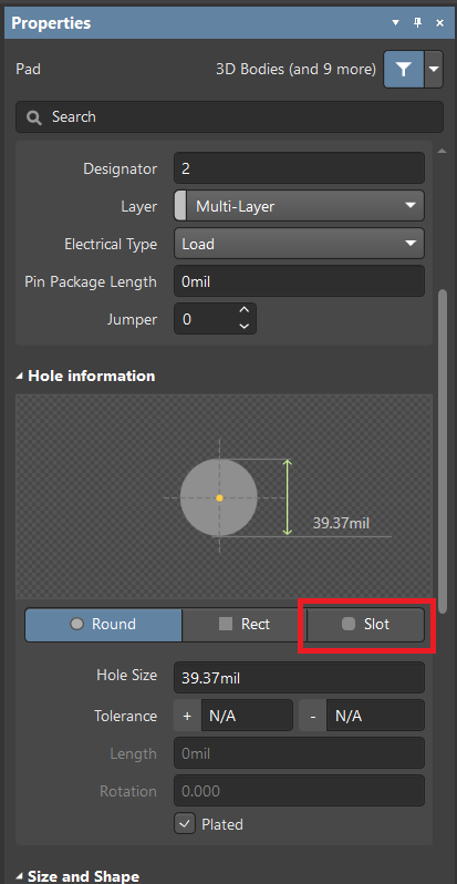
1.Double-click on the pad to show Properties.
2. Under Hole information, change Round to Slot. (See Figure 1)
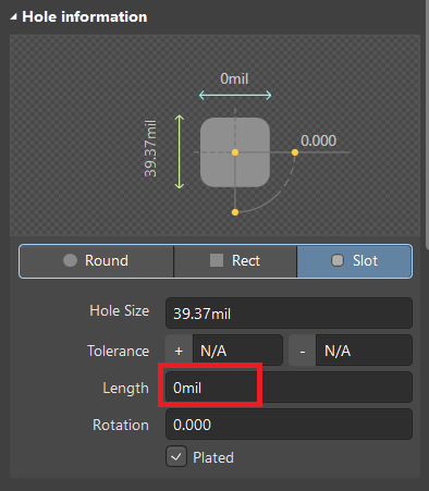
3. Adjust the length appropriately. (See Figure 2)