

How to make global fiducials in Allegro
Fiducial reference points are necessary in a circuit board if you are going to assemble your PCB using automated pick and place machines. Automated assembly machines require incredible precision to accurately place a 0201 size resistor or a 2mm x 2mm chip-scale micro BGA.
A fiducial is the reference point on the PCB for assembly machines. It helps the machine to recognize your board orientation and direction. Fiducials can be placed on the top copper layer; they are not placed on the mask or silk layers, because they are not as precisely aligned to the parts as the copper layer itself.
There are global and local fiducials. Global fiducials are used to locate the position of all of the land patterns on a PCB. A local fiducial is used to locate the position of an individual land pattern on a PCB.
Below you’ll see the steps needed to make global fiducials in Allegro, where we use two fiducials on either corner of the PCB. The farther away they are, the better the precision.
Fiducials can have many different shapes: they can be circular, square, triangular, diamond-shaped, and so on. Most commonly, they are circular, and their typical size is 1.0 mm (dia) for the copper pad with a 2.0 mm (dia) stop mask. A keepout of 3.2mm dia is needed around the fiducial to avoid having planes or traces under the fiducials.
Steps to making global fiducials in Allegro 16.6:
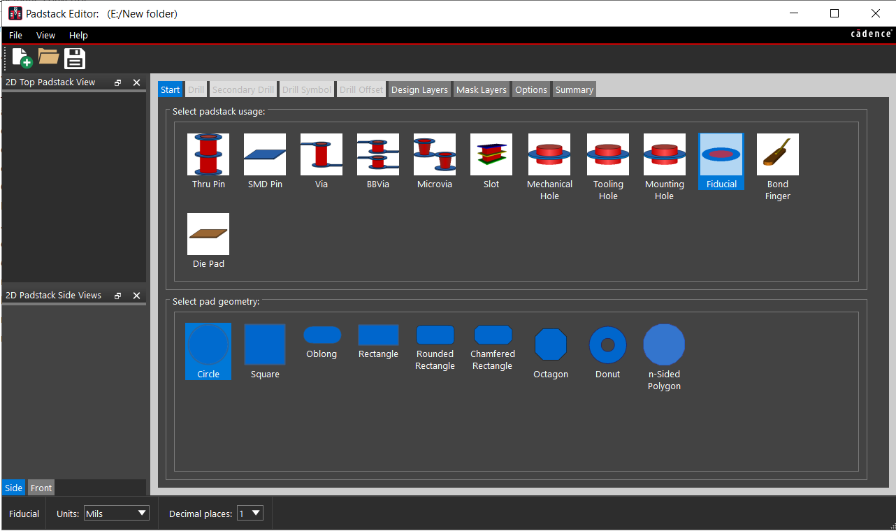
Step 1. Open padstack editor – start – select Fiducial option in the padstack usage – select the pad geometry
Go to Design layer – set the circle dia as 1mm in the begin layer, then select Mask layer – set soldermask top as 2mm – save the padstack

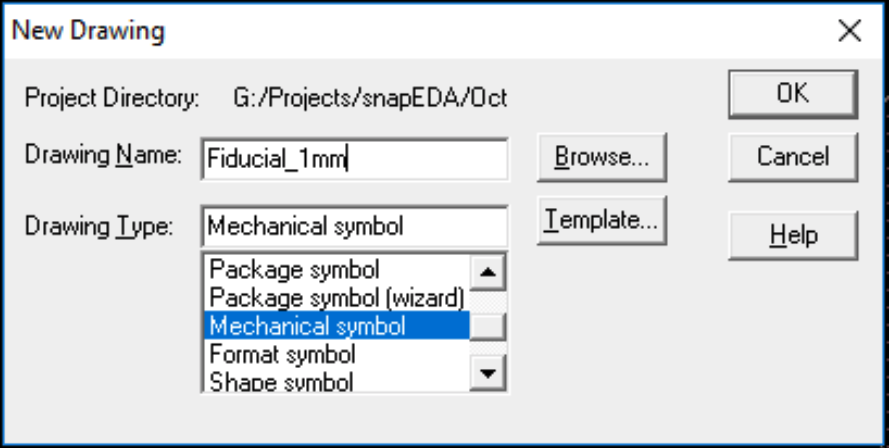
Step 2. Open Allegro PCB Librarian XL, then go to File and click on New. Enter the Drawing Name, after that click on Drawing Type, select Mechanical symbol and finally click OK.
Step 3. Go to Layout, then go to Pins. Select Padstack and then place the padstack at the origin (0,0). After that, right-click and then click on Done.

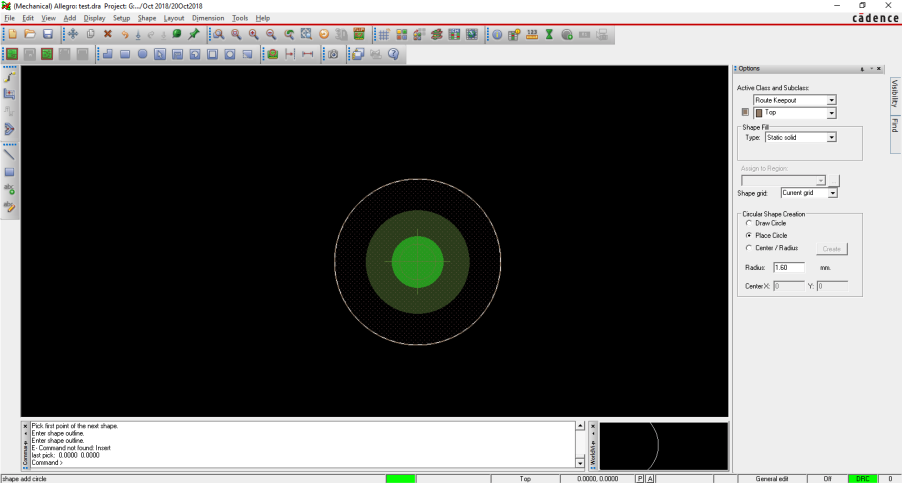
Step 4. Go to Shape, then select Circular. After that, set Class/Subclass as Package Keepout/Top, and then select Place circle at the options tab. Set Radius as 1.6mm and place the circle at the origin (0,0).

Step 5. Repeat step 4 with Class/Subclass as Route Keepout/Top
Step 6. Save the design
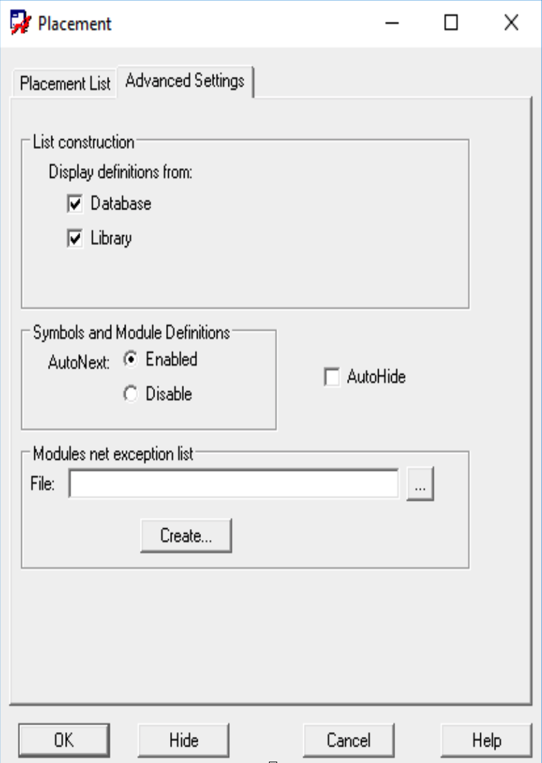
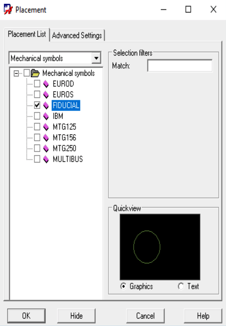
Step 7. Open PCB editor – Place – Mechanical symbol – select the symbol that you created – Place it. Finally right-click and then click on Done
Comments (5)
Arsalan Azhar
February 11, 2019 at 3:59 pm
Hi, Fiducials can be of any shape like in we draw plus like symbol with circle in center like this ❇️ in top and bottom etch layer.
admin
February 23, 2019 at 4:36 am
Hi Arsalan! Thanks a lot for the feedback. We will update the blog post to reflect this.
Damian holland
March 17, 2021 at 10:43 am
Hi guys, this needs updating: To be able to utilise the Manufacturing, design for Fabrication DRC checks (V17.2) the pad being used in the fiducial needs to be defined as a fiducial pad, not just an SMD pad. So for checking silkscreen legend to fiducial spacing for example.
Faust Arenas
January 30, 2023 at 8:52 am
Hi Damian,
Thanks for your suggestion. We’re going to forward this to our engineers for confirmation and have our team update this blog post. We will keep you posted on this.
Ron Publico
May 8, 2023 at 4:20 pm
Hi Damian,
Thanks for reaching out! We are want to let you know that we were able to make some updates on the blog 🙂
Again, thank you so much for your feedback. We really appreciate it.