
Best practices: How to map the footprint courtyard and cutouts to the proper layers in Altium
If you’ve downloaded a footprint from SnapEDA for Altium, then you may have wondered how to properly import the courtyard and cutout layers.
When importing the file, you need to map the placement courtyard to Mechanical Layer 15, and the board cutout regions to Mechanical Layer 1. In the video below, we’ll show you how to map these layers during the import using the P-CAD importer, which is the format we export to for import into Altium.
Steps to import:
1) Download the Altium file from SnapEDA: Search for the desired part on SnapEDA’s website and download the footprint and symbol in the Altium format.
2) Import to Altium: Open Altium, click on File > Import Wizard
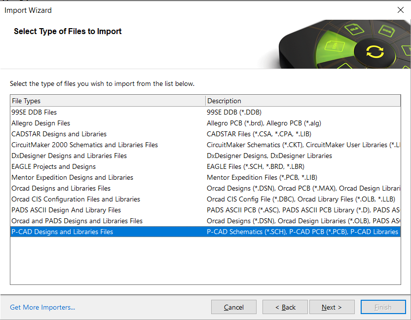
3) Choose the .lia file to import: Click Next and select P-CAD Designs and Libraries Files, then click Next.
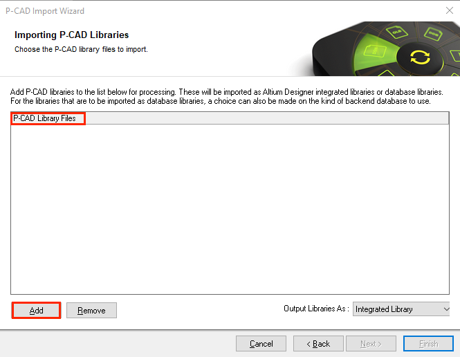
Important: Please click on ‘Next’ again and make sure you are in P-CAD Libraries Files window, then click Add and select the .lia file.
 Click Next until you reach Current Layer Mapping window
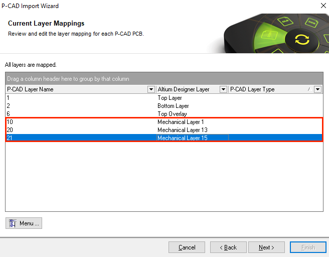
4) Select Mechanical Layer 1: In “Current Layer Mapping” import step, for the cutout layer, choose: ‘10’: Mechanical Layer 1.
5) Select Mechanical Layer 15: In “Current Layer Mapping” import step, for the courtyard layer, choose: ‘21’: Mechanical Layer 15.
6) Select Mechanical Layer 13: In “Current Layer Mapping” import step, for the documentation layer, choose: ‘20: Mechanical Layer 13.
7) Click Next and follow the remaining prompts, then click Finish
8) Start designing!
After this simple steps, you are ready to start design in Altium with your SnapEDA footprints and symbols.